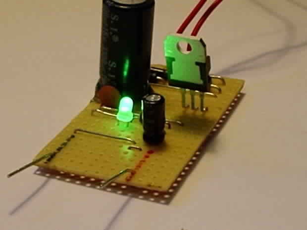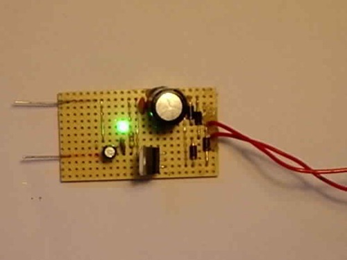
Step 1: Things that you will need…

- Piece of veroboard
- Four 1N4001 diodes
- LM7812 regulator
- Transformer that has an output of 14v – 35v AC with an output current between 100mA to 1A, depending how much power you will need. (I found a 16v 200mA transformer in a broken alarm clock.)
- 1000uF – 4700uF capacitor
- 1uF capacitor
- Two 100nF capacitors
- Jumper wires (I used some plain wire as jumper wires)
- Heatsink (optional)
You should be able you get most (maybe all) of the parts at Radio Shack or Maplin.
Step 2: And the tools…

- Soldering iron
- Wire cutters
- Wire strippers
- A thing you can cut veroboard tracks.
- Hot glue (To hold components down and make the power supply physically strong and sturdy.)
- And some other tools that you might find helpful.
Okay, I think that is about it, lets get to work!
Step 3: Schematic and others…

However, if you are just going to pull out a few hundred milliamps (lower than 500mA) from it, you won’t need a heatsink for the regulator, but it may get a little bit warm.
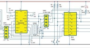
Also, heres the schematic…
I also add in an LED to make sure the power supply is working. You can add in an LED if you want.
Step 4: Make it!

Make sure you get good solder joints and no solder bridges, otherwise your power supply won’t work!
Oh, If you don’t know how to solder, read this great article about how to solder!
Step 5: Test it!

After you tested it, put it in a plastic box or something to protect you from shocks.
But do not operate the power supply like I did, it is very dangerous because of the mains voltage on the transformer, you or somebody will get badly shocked!
My power supply has 11.73v output, not too bad, I don’t need it to be exactly 12v…
Step 6: Done…

But again do not operate it without any protection!
If you need any help, or questions, or any thing, make a comment!


I tend to use an old PC power supply with a breakout board
http://dangerousprototypes.com/docs/ATX_Breakout_Board