

 The aim of this article to make a laser light security alarm and it can also be used as a home security system. The essence of this project is that anyone can make it at home to save their home from thefts.
TOOLS REQUIRED
- Soldering iron
- Soldering flux
- Solder wire
- Small hand drill machine
Components Required
- Plain PCB (printed circuit board)
- Scrubber
- PCB etching
- Double-sided tape
- Resistor 100 Ω – 03nos.
- LDR (light dependant resistor)-01no.
- LED (light emitted diode)-01no.
- Transistor (BL548) -02 nos.
- Buzzer
- Switch
- DC socket (Nokia cellphone small charging pin)
- Adapter -5volt (nokia charger)
- Battery holder
- Battery
- Laser light
- Switch
Construction & Testing
Step 1
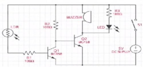
Tracing the circuit
Take a permanent marker and make a rough layout or path draw on your PCB as shown in figure 1.

Step 2
Clean the PCB with the help of a scrubber and after taking a small size container and some PCB etching solution (Ferrous Chloride), prepare a solution of etching by mixing the ferrous chloride and water in a container. Dip PCB into solution and shake it for 10 minutes, now take out the PCB and wash it thoroughly.
Step 3
Drill few holes on PCB with the help of small hand drill for mounting other electronic components.
Find the location of electronic components from layout and placing them carefully on their respective positions.
Solder the electronic components on PCB and assemble the laser light and solder it carefully with the battery holder and also solder a switch to positive terminal of battery holder.
Step 4
Final step
Carefully placed the battery holder and after checking the output voltage of circuit with a multimeter.
After checking the circuits again for proper placement, press the switch ‘ON’.
Now, when you put your finger in front of laser, you will find that the buzzer would turn on thus producing an alarm. When you ‘OFF’ the switch the buzzer will not make any sound.
Your Security System is ready.
Shri Himadree Bhusan Sahoo is an Electrical Engineering student and Electronics Enthusiasts
This content was originally published here.


