

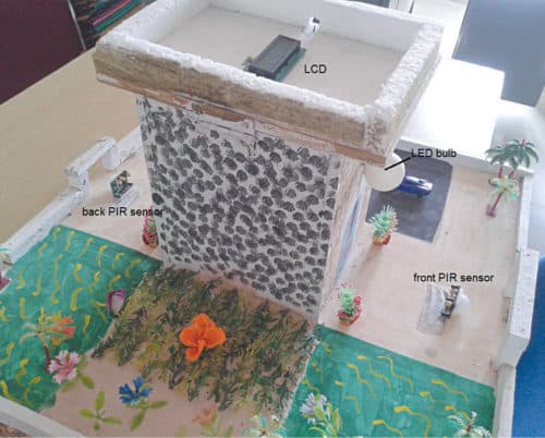
This project demonstrates a wireless security system in which four pyroelectric infrared (PIR) motion sensors are placed in four sides—front, back, left and right—of the area to be covered. It detects motion from any side and turns on the audio-visual alarm. It also displays the side where the motion (intruder) is detected. All sensors send signal to the central controller circuit wirelessly. The author’s prototype arrangement is shown in Fig. 1.
System block diagram
System block diagram of the wireless security system is shown in Fig. 2. The project uses PIR motion sensors to detect motion and ASK-based radio frequency (RF) transmitter and receiver modules to send signals wirelessly. It uses AT89S52 microcontroller (MCU) and LCD to display the side where the motion is detected.
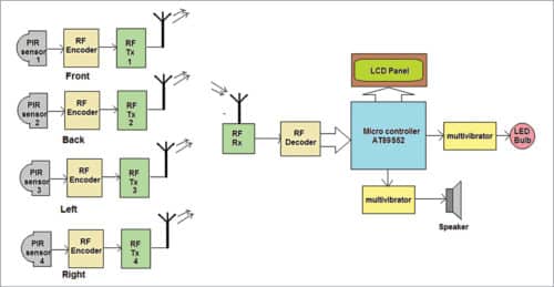
The block diagram has two parts: four transmitter units with PIR sensors, encoders and RF transmitters; and receiver unit with RF receiver, decoder, MCU and some audio-visual circuits.
Transmitter unit
There are four transmitter blocks, one each for front, back, left and right sides. Each block consists of a PIR sensor, RF encoder chip and RF transmitter (Tx) module.
PIR sensor
The PIR sensor detects motion by measuring any change in IR levels emitted by objects. Pyroelectric devices have elements made of a crystalline material, which generate an electric current when exposed to IR radiation. Changes in the amount of IR falling on such devices changes the voltages that are generated. Sensor output goes high when it detects motion. Sensor output is given to RF encoder chip.
RF Encoder
HT12E encoder chip encodes PIR sensor output into serial bit streams and gives it to RF Tx module.
RF transmitter
ASK transmitter modulates incoming digital signals from the RF encoder using a 434MHz carrier and transmits it through its antenna.
Receiver unit
This is the central controlling section that receives signals from any of the four PIR sensors at the transmitter side. It gives audio and visual alarms, and displays the side where the motion is detected on LCD1.
RF receiver
This module operates on 434MHz frequency and demodulates the received digital signals before sending bit streams to RF decoder chip.
RF decoder
HT12D RF decoder chip decodes bit streams and generates parallel 4-bit digital output, which is given to the MCU.
MCU
AT89S52 MCU performs the following tasks:
1. Detects side where motion is detected from RF decoder digital output
2. Displays various messages including side of detected motion on LCD1
3. Turns on speaker and blinks LED for audio-visual alarm when motion is detected
LCD panel
The 16×2 LCD panel displays messages given by the MCU.
Multivibrators
There are two multivibrators. One for blinking the LED at low frequency (1Hz – 2Hz), and the other for generating the audio frequency signal (1kHz) through the speaker for siren.
Circuit and working
There are five circuits. Of these, four transmitter circuits are similar to each other, with minor changes, as shown in Fig. 3. Fifth circuit, as shown in Fig. 4, is the receiver circuit.


Transmitter circuit
The first transmitter circuit is built around IC1. Output of PIR sensor PS1 is given to data input AD8 (pin 10) of HT12E (IC1) after inverting it through transistor T1. Diodes D1 and D2 connect transmission enable (TE) pin with pin AD8, so that both pins get input from the sensor at the same time.
LED1 is connected to collector output of T1, so that it blinks when PS1 sensor output goes high. Address pins A0 through A7 of IC1 are connected to ground to set address 00 (0000 0000b). Serial data output DOUT (pin 17) is given as data input to 434MHz RF Tx module (TX1). The whole circuit is given power through 6V battery (BATT.1) connected across CON1.
The other three circuits are shown in Fig. 3 are similar to the one described above. The only difference is that the diode is connected to different data pins.
When PIR sensor PS1 detects motion, its output goes high. T1 conducts and LED1 blinks.
Pins AD8 and TE of IC1 are pulled low together through diodes D1 and D2. When TE pin is pulled low, IC1 transmits address A0 through A7, and AD8 through AD11 serially through RF Tx module. Because pin AD8 is pulled low, data bits are transmitted as 1110 (AD11 through AD8). Similarly, in other such circuits, when motion is detected, the respective data pin is pulled low, so different data is transmitted, as listed in Table I.
Thus, when a sensor detects motion from its side, different bit pattern of D0 through D3 is transmitted. At receiver side, this pattern is used to identify the side where motion is detected.
Receiver unit
As shown in Fig. 4, the receiver is built using 434MHz RF Rx module (RX1), RF decoder chip HT12D (IC5), AT89S52 MCU (IC6) and NE555 multivibrators (IC7 and IC8).
This content was originally published here.


